

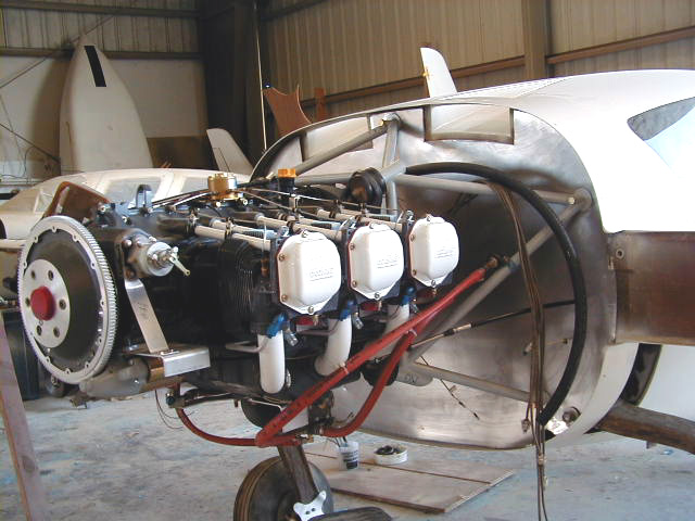
June 21, 2001 - My engine arrives!! It is a Lycoming IO-540C4B5 equipped with one Jeff Rose Electronic Ignition and one Slick Magneto. The engine was overhauled to 0 time status by Don George, Inc. in Florida. Don and his company are superb and offer outstanding customer service in addition to work of the highest quality. The mounting process and installation of plumbing, controls and accessories are illustrated below.
A modification of theASC Homebuilder's Oil-Air Separator is detailed below. A brass fine mesh screen was placed inside the device. This modification has proven amazingly effective (and inexpensive!) - I have seen virtually no oil on the plane's belly at all.
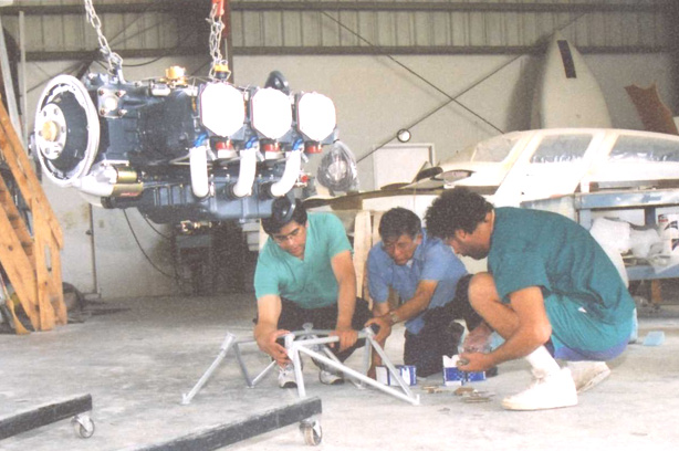
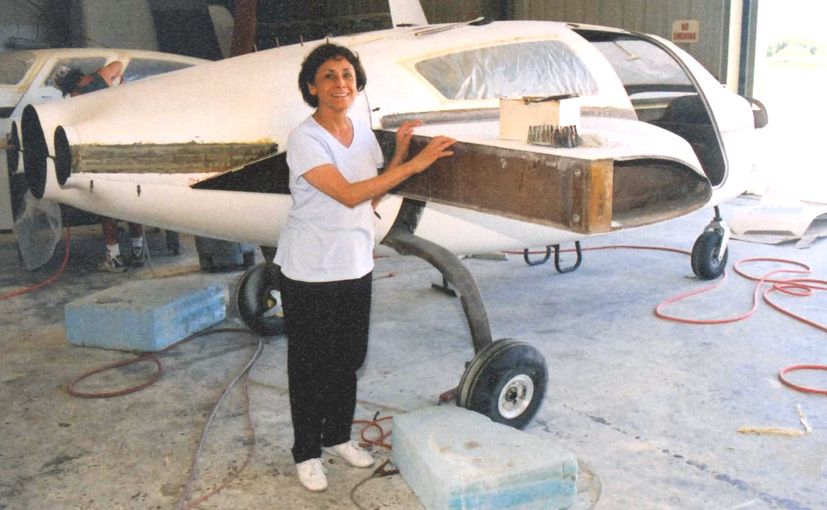
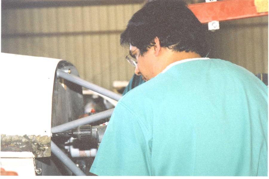
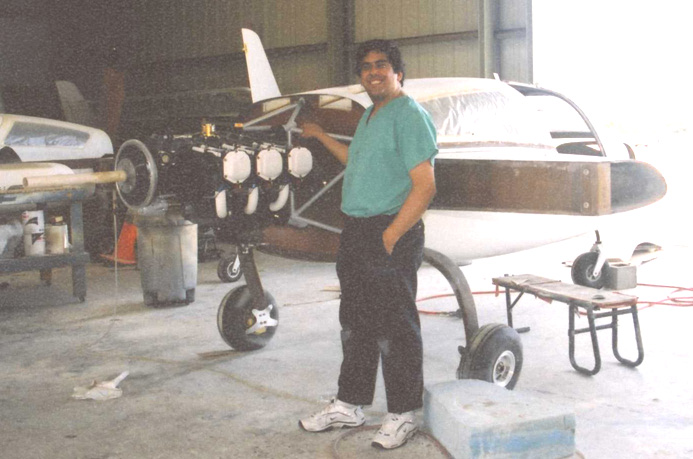
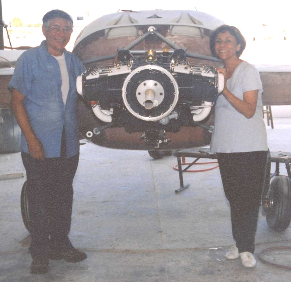
My parents, Ricardo Sr. and Inez, were brought in to assist in the initial stages of mounting and installation.
Details of installation of engine preheater system from Reiff, fuel pump installation, engine plumbing and instrumentaton are also seen below.
Mitsubishi 60 amp alternator obtained from Mark Landoll's Electrical Service, 405-392-3847 at 1205 Redbud Lane Newcastle, OK 73065. Mr. Landoll has been supplying alternaters to homebuilders for years and can quickly service just about any need for aircraft power.
Additional photos added as engine installation completed through January 2002.
Click on thumbnails to view larger versions of the pics!
|
|
|
|
|
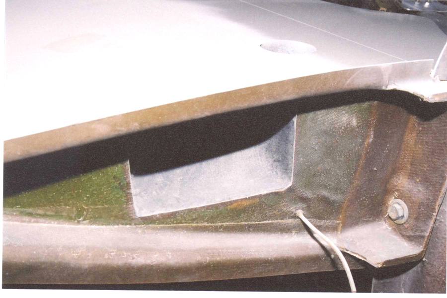
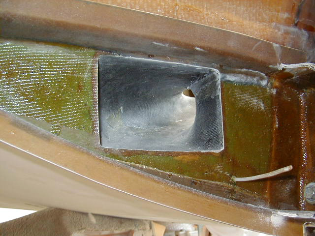
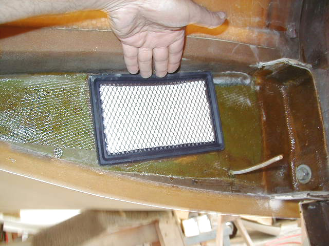
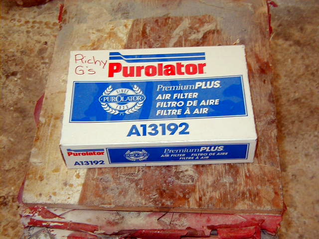
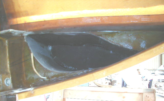
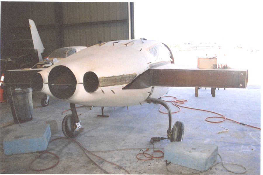
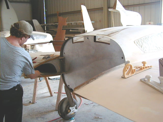
| View of air duct carved in wing. An oval intake scop will be attached over opening in lower wing surface seen top center of photo. | Induction air duct carved into wing. | Air filter in place in wing root. | Air filter used in previous shot. |
|
|
|
|
|
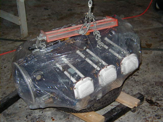
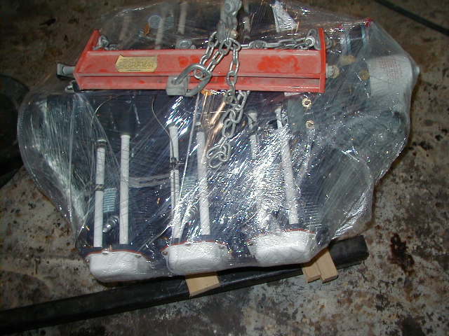
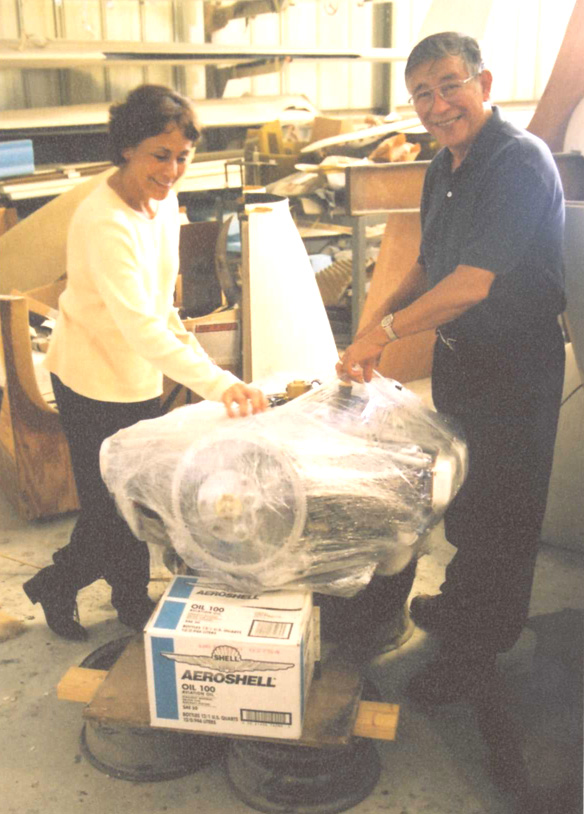
| Oil cooler recess carved into wing root. | It's like a monstrous Christmas present! | Another view of the engine, soon to be unwrapped and installed. | Mom and Dad get an early Christmas present! |
|
|
|
|
|
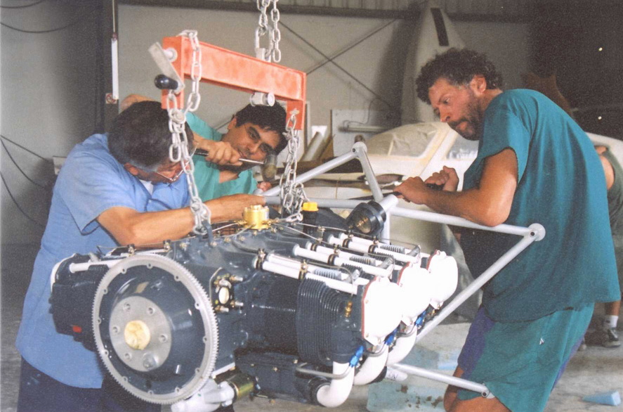
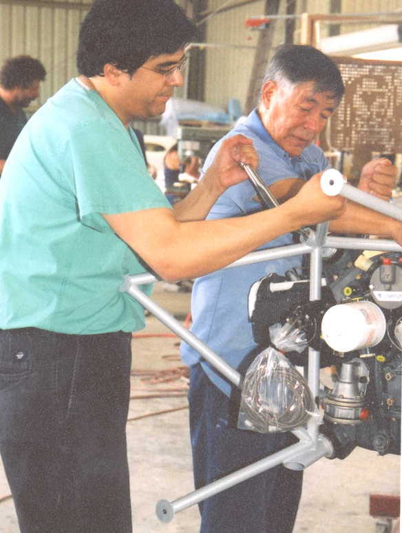
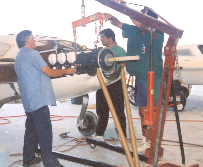
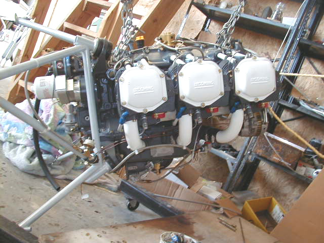
| After unwrapping the engine, it is hoisted up to make working underneath it and attaching the mount easier. My father appears satisfied by the work done by Don George, Inc. (which is superb) | Malcolm, my father and I preparing the engine mount obtained from Velocity for bolting on to the engine. | The mount is bolted to the engine at 5 points which are angled inwards toward the center of the engine. The mount fits perfectly when the bolts are in place and the mount is snugged in the engine. After placing 4 bolts in place, the last one requires a little convincing. Here Malcolm applies a little persuasion with a pry bar, my father pulls and I tap the bolt into position. | My Dad and I torquing the engine mount bolts into position. |
|
|
|
|
|
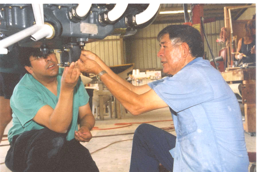
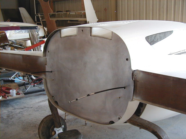
| Attaching the fuel servo elbow. | My mother, Inez, posing next to the cowling which is clecoed into position. This will allow positioning of the engine in the center of the cowling. | Another view of the cowling in place. | |
|
|
|
|
|
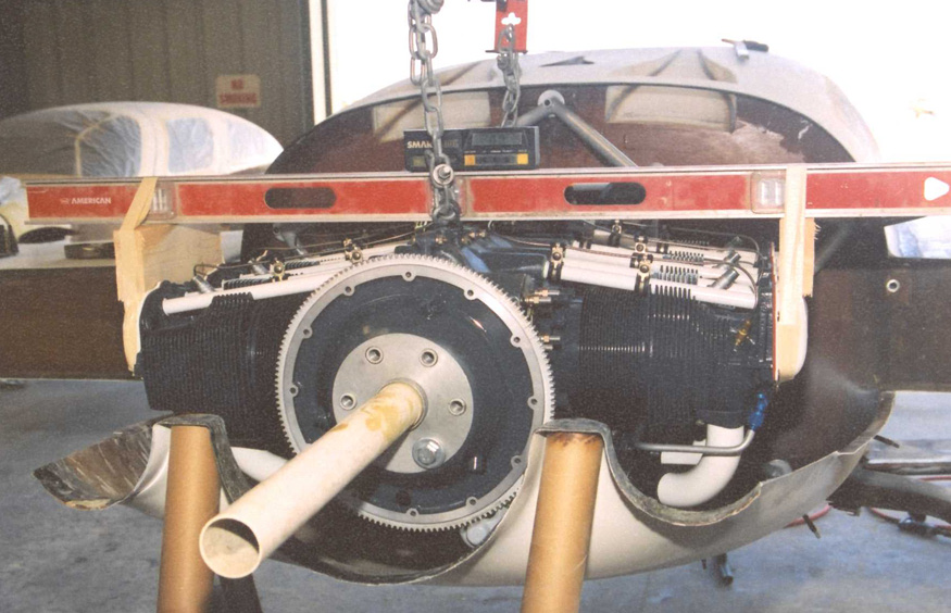
| After determining the center of the cowling, the upper half is removed and the lower is propped into position. The engine is lowered into place from above and the process of leveling in all axes is begun. | A digital level is set into position across the engine. The PVC tube is used to determine the position of the prop and used to help center the engine within the cowling. | After much tweaking, the engine is ready to be mounted. | Drilling engine mount holes. First the topmost bolt hole is shot to "pin" the engine into place at least in one axis. |
|
|
|
|
|
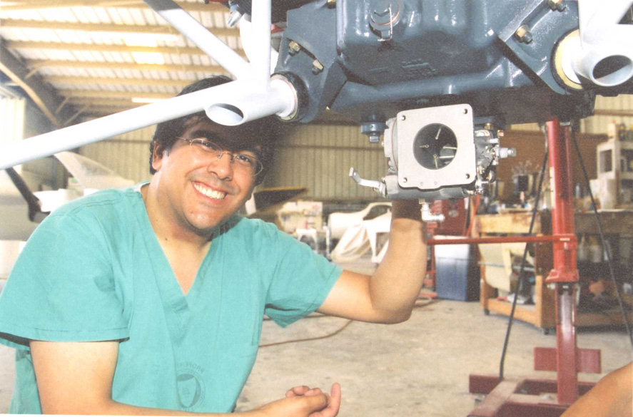
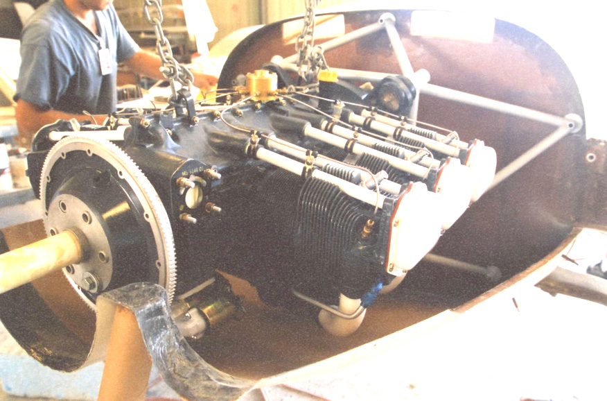
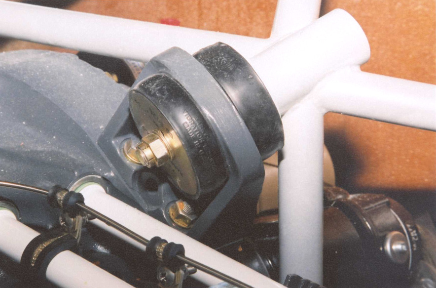
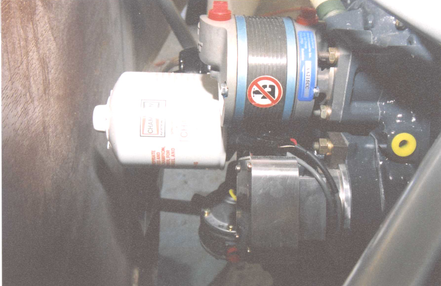
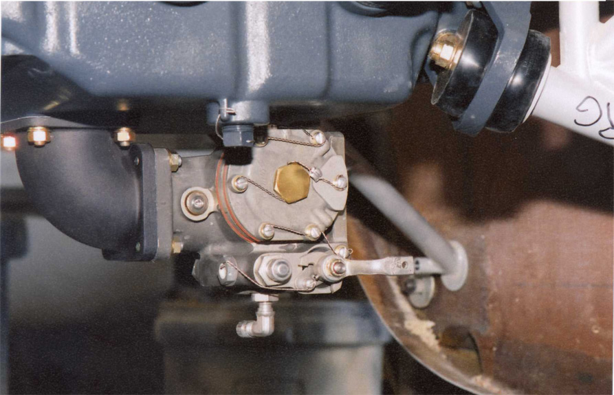
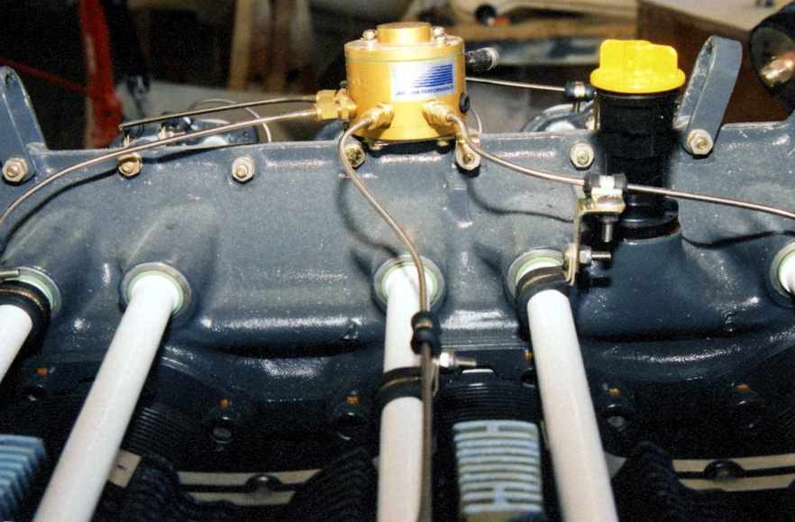
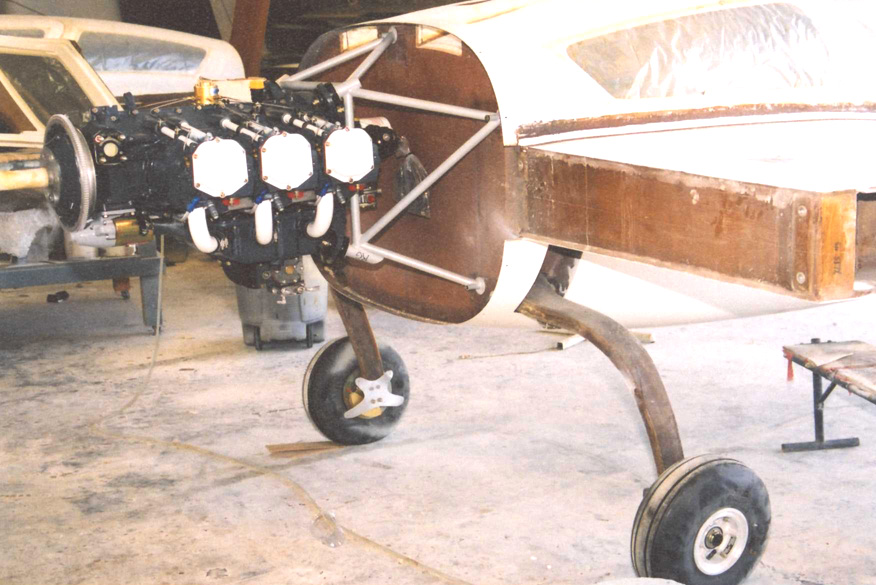
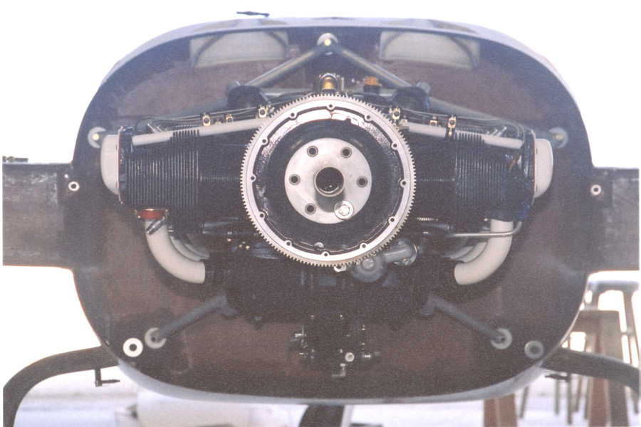
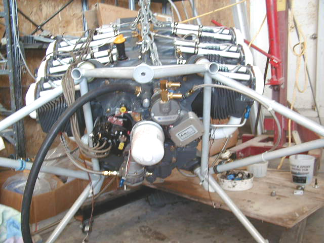
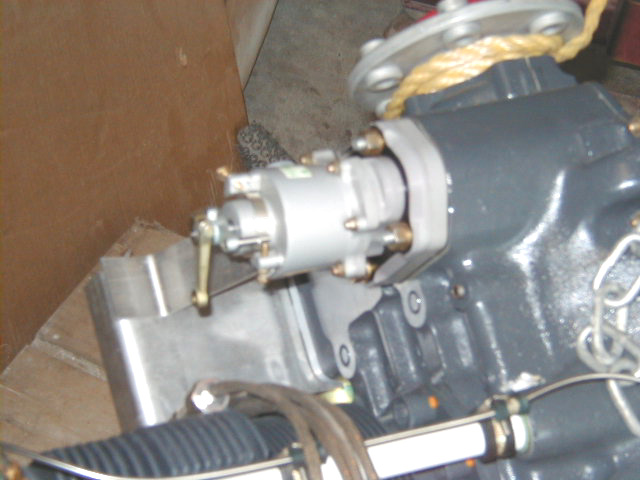
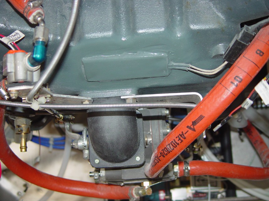
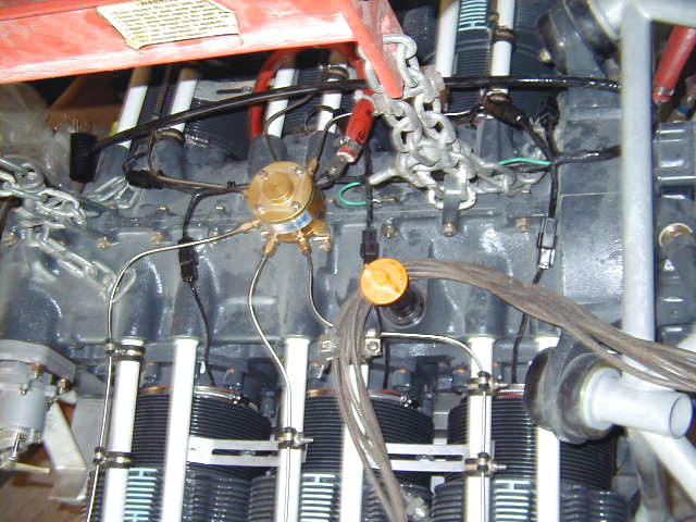
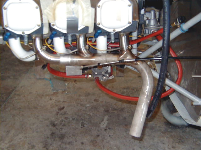
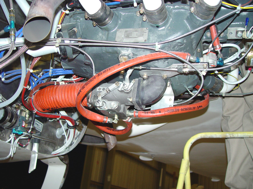
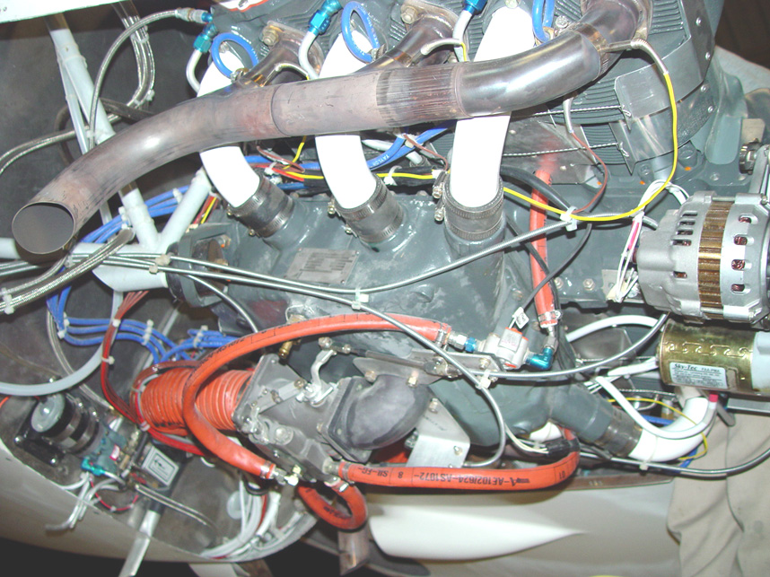
| Barry rubber mounts seen here at one of the mounting points. | Engine detail: top center is vacuum pump, white oil filter center, Electroair electronic ignition lower center with mechanical fuel pump behind. | Fuel servo seen here under engine. | Fuel injection spider located on top of engine. |
|
|
|
|
|
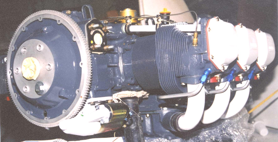
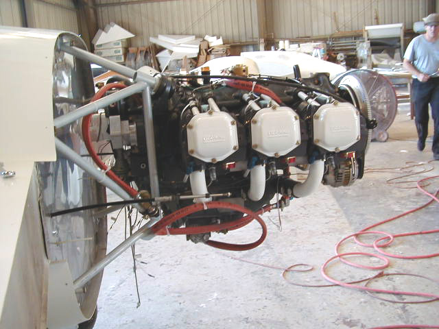
| SkyTec starter seen lower left of photo. Hydraulic prop governor will be attached to bolts seen upper left side of photo. | Engine now temporarily mounted in place. | My parents, Ricardo Sr. and Inez. | View of mounted engine. |
|
|
|
|
|
| View of mounted engine from rear. | Engine in place with cowling attached. It fits! | Installing the stainless steel firewall. | |
|
|
|
|
|
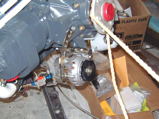
| Plumbing started on engine accessories. | Plumbing and CHT's on left side of engine. | MT prop governor seen near center of pic. | Alternator and fuel flow sensor. |
|
|
|
|
|
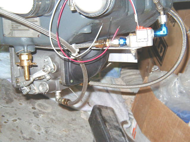
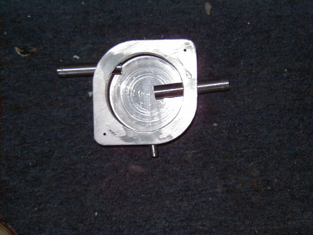
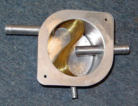
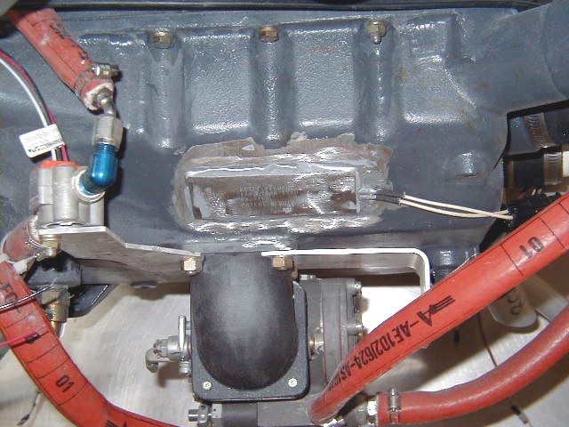
| Fuel flow sensor and fuel servo plumbing. | Fuel pressure sender. | Inside the oil-air separator. This is an ASC homebuilder's Oil-air separator. We are going to add a section of wire screen to improve condensation oil from the oily air from the engine to decrease blowing the stuff overboard. | Fine brass mesh placed inside the oil-air separator. The Homebuilder's Oil-air separator made by ACS was modified such that it can now be opened for servicing, the mesh was installed, and the intake and output was reversed as labelled by the factory. Air from engine now flows in from port at right and blown overboard from port at top left. Oil condenses on mesh and drips down to be returned to engine via bottom port. No more greasy belly? We'll see! |
|
|
|
|
|
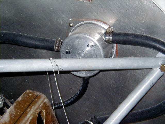
| Oil-Air Separator mounted on firewall with ports relabeled. | A Reiff HotStrip Oil Sump Heater and HotBandd Cylinder Heater System was installed for those cold winters. Here, sump heater seen epoxied to oil sump. The harness connects to the cylinder heaters in the next photo to form a multi-point preheat system. See the Reiff Preheat Systems web site for details on this system. | Reiff HotStrip Oil Sump Heater installed. | Reiff HotStrip Oil Sump heater with epoxy cured. |
|
|
|
|
|
| Reiff Hotbandd Cylinder heater seen encircling the bases of each cylinder. | Stainless steel firewall in place, ready for permanent engine installation! | IO-540 bolted into position. | |
|
|
|
|
|
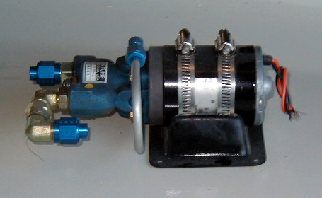
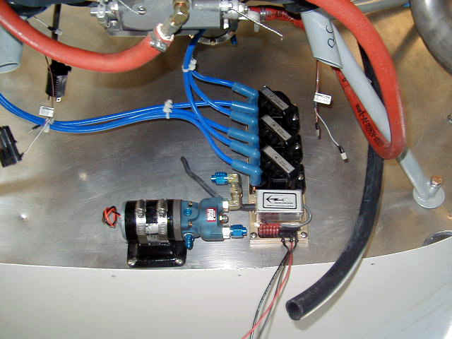
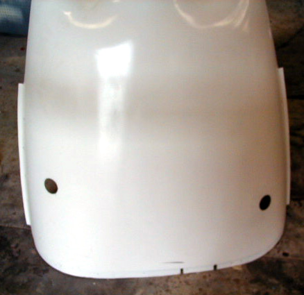
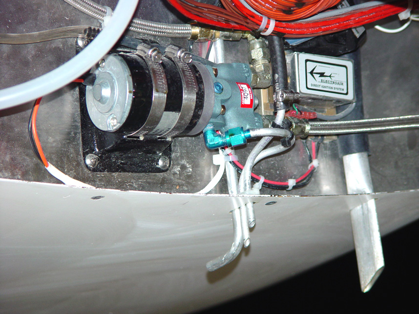
| A fuel pump mounting bracket which is a molded part specially made by Hangar 18 which is very sturdy, weighs about 6 ounces, and mounts anywhere. | Looking from below, Wheldon fuel pump and ElectroAir Electronic ignition installed on firewall. | Exhaust header and EGT sensors. | Exhaust header holes in lower cowling. |
|
|
|
|
|
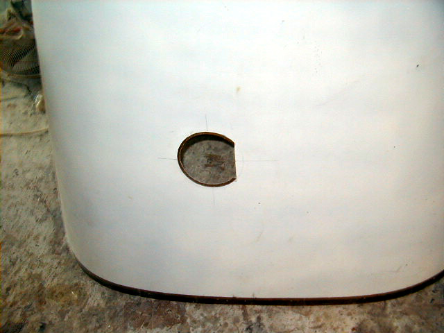
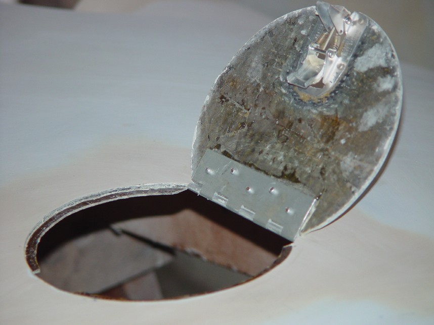
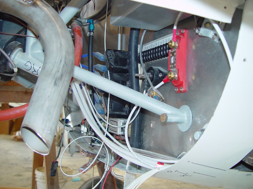
| Oil check door opening cut in upper cowling. Plug for Reiff Heater will also be accessible through here. | Oil access door finished! | Electrical harness from Velocity installed. Note alternator fuse upper right corner. Please note that this harness was designed for a generic factory installation and for analog engine instrumentation. In particular, the Vision Microsystems instrumentation uses custom wiring which they provide making most of the engine wires in the harness redundant. The strobe cables assume an installation of driving unit within the cabin rather than in the strake which is where mine were installed. Once you decide what you are going to use I would recommend careful inquiry and discussion with Wayne Lanza at Velocity regarding compatability with your equipment before purchase. | A look underneath the engine. Note the heat shield protecting the S-Tec roll servo upper right hand corner. |
|
|
|
|
|
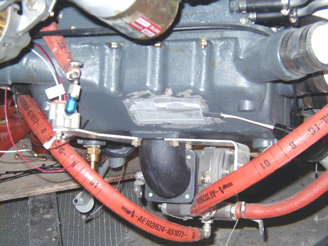
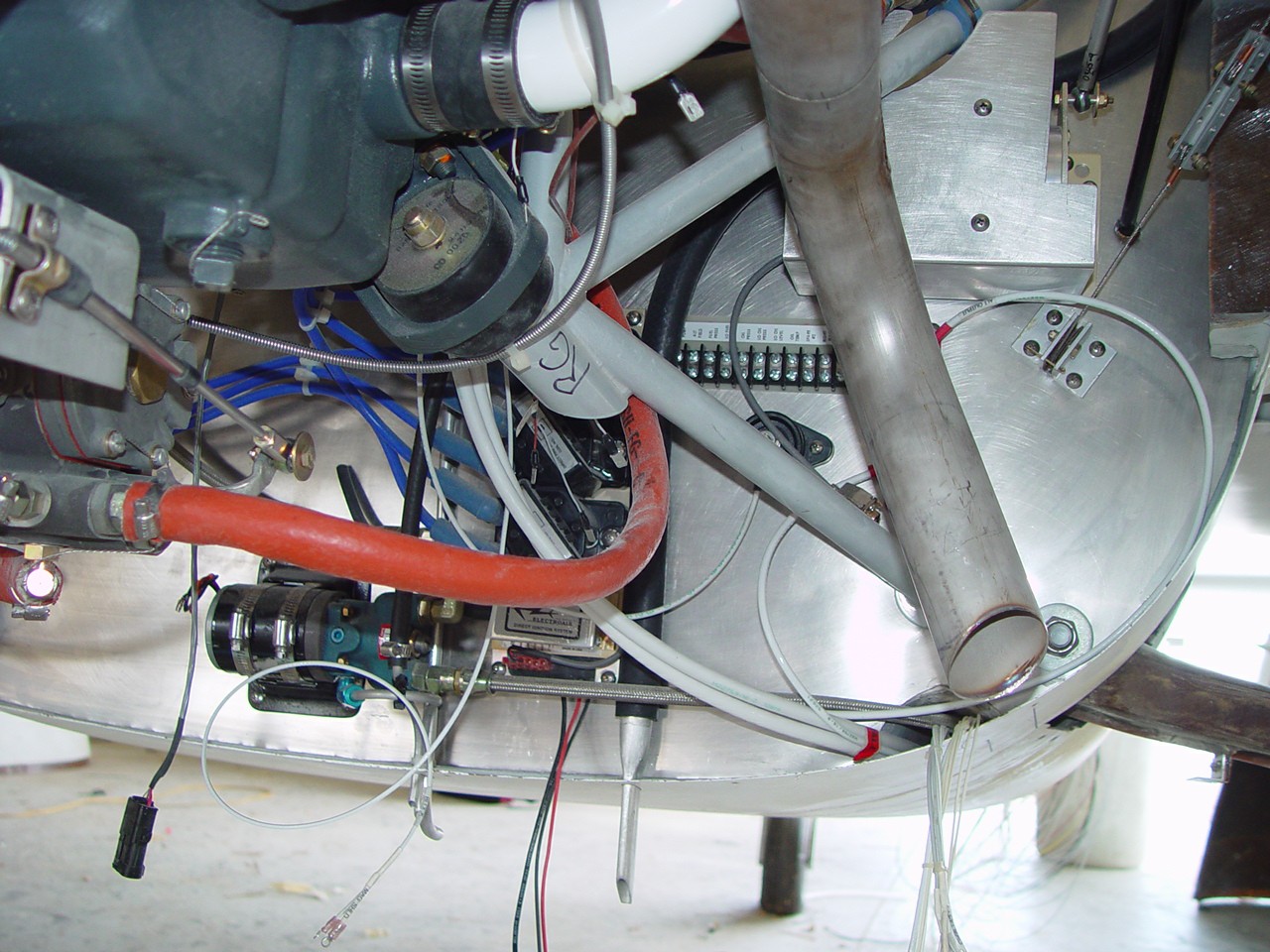
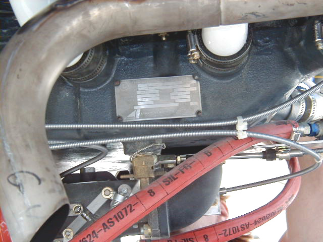
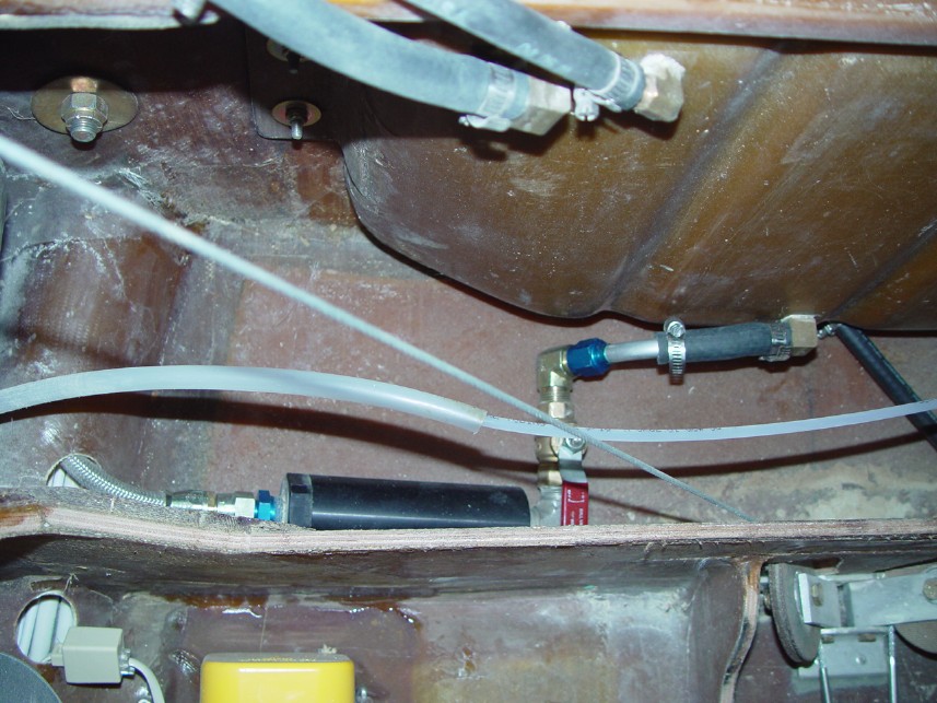
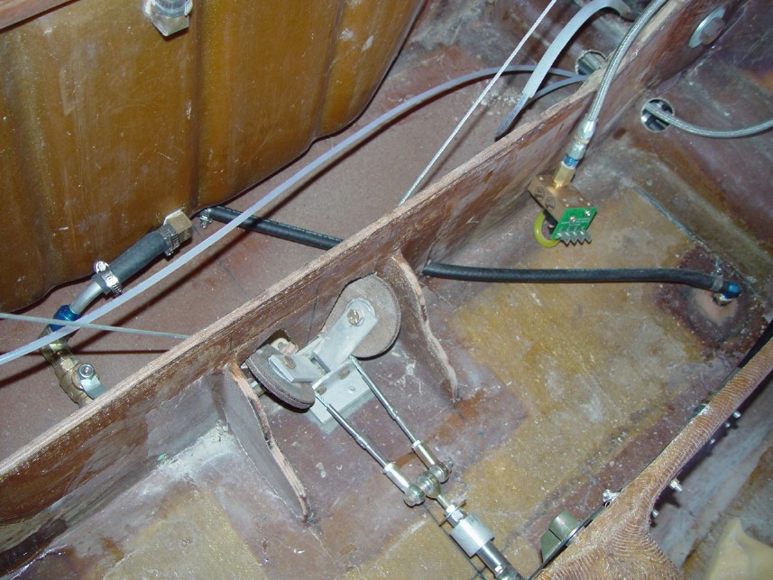
| Another peek under the engine compartment. | Data plate for the Lycoming IO-540C4B5 engine attached to oil sump under the cylinders. | Inside the cockpit on the other side of the firewall: sump tank with fuel lines entering from copliot side strake tank upper center. Fuel line passes from sump tank center right through fuel shutoff valve, fuel filter then out through firewall via wire ducts along fuselage left center. | Fuel system drain seen exiting from under sump tank at its lowest point, passing forward and toward pilot side where it passes through the floor to drain seen in next photo. This places the drain in a more convenient place. |
|
|
|
|
|
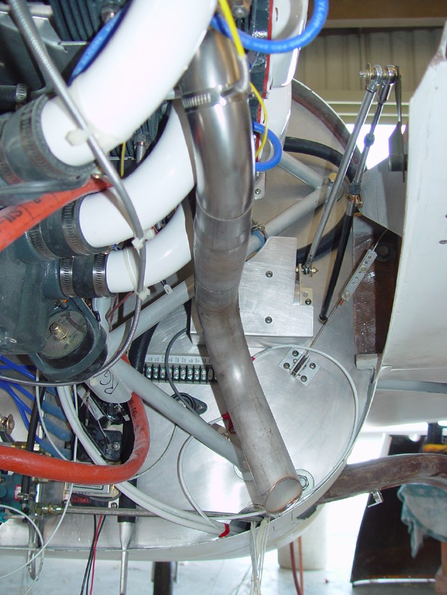
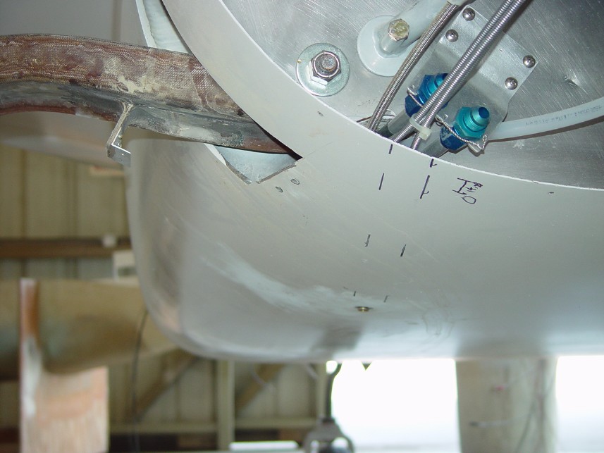
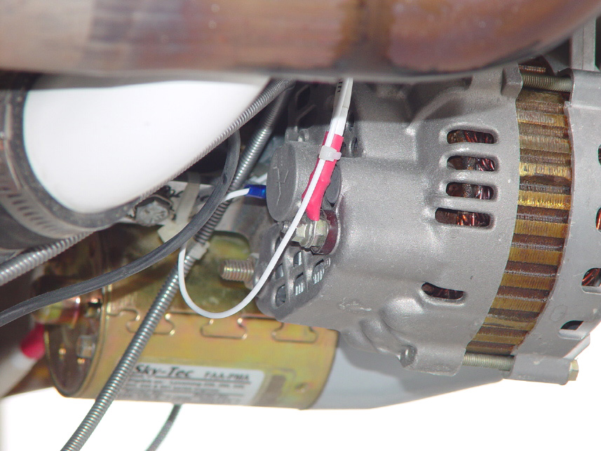
| Fuel system drain seen near center of photo. 12/4/01 - To clean out the system, 15 gallons of 100LL were added into the tanks, "swished" around by rocking the plane and then drained. Out of 15 gallons, a little over 14 were recovered leaving the unusable fuel at less than 1 gallon. | Closeup of the alternator. Alternator field wire now installed. Funny how the battery won't charge without it! | Detail of underbelly of engine. | |
|
|
|
|
|
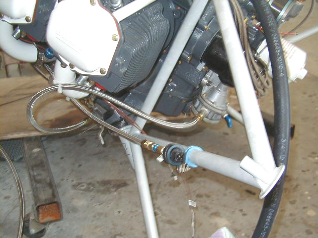
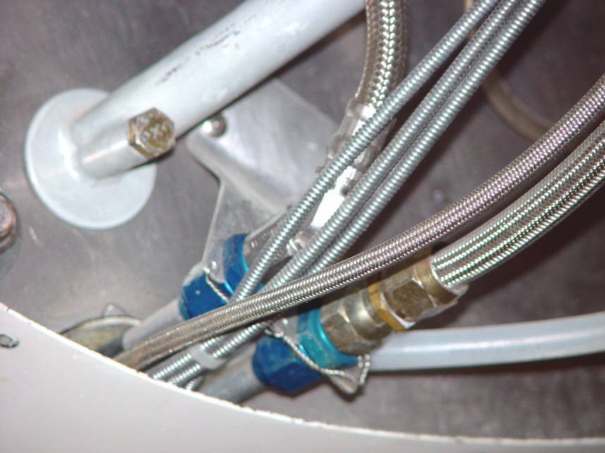
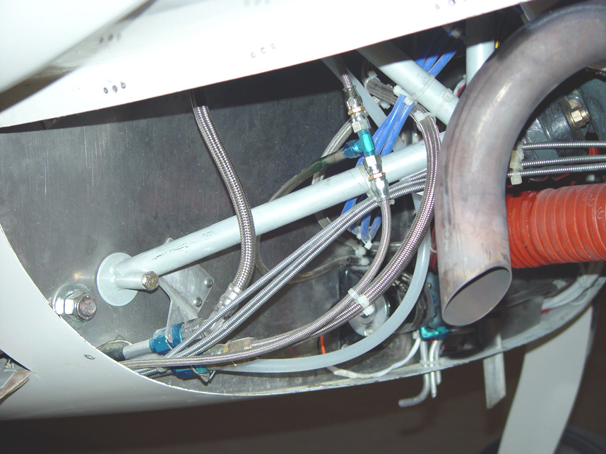
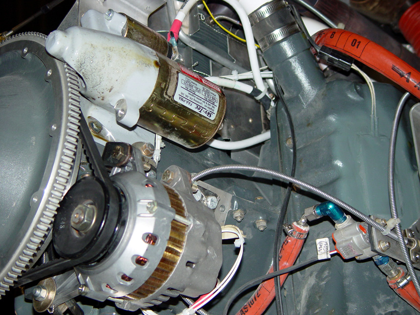
| Closeup of fuel pump showing fuel tank vent (angled forward like a pitot tube) protruding down from belly of fuselage. Oil/air separator outlet seen to far right of photo. THe modified separator has proven to be extremely effective with virtually no oil being spewed out onto the plane's belly! A LOT less expensive than the some of those commercial versions! | Control cables for throttle, prop and mixture and oil cooler lines exiting pilot side conduit. | Another view of cables and oil lines. | Closeup of alternator and starter. |
This page visited times.
 Comments, questions, and suggestions are welcome! email: rich@rguerra.com
This page created on a Macintosh using PhotoPage by John A. Vink.
Comments, questions, and suggestions are welcome! email: rich@rguerra.com
This page created on a Macintosh using PhotoPage by John A. Vink.