Click on thumbnails to view larger versions of the pics!
|
|
|
|
|
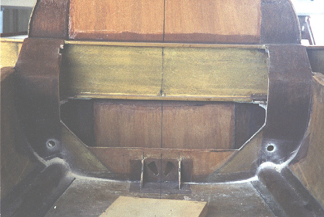
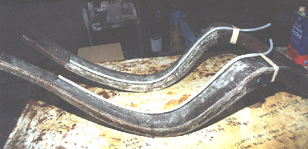
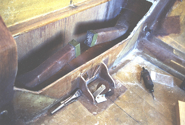
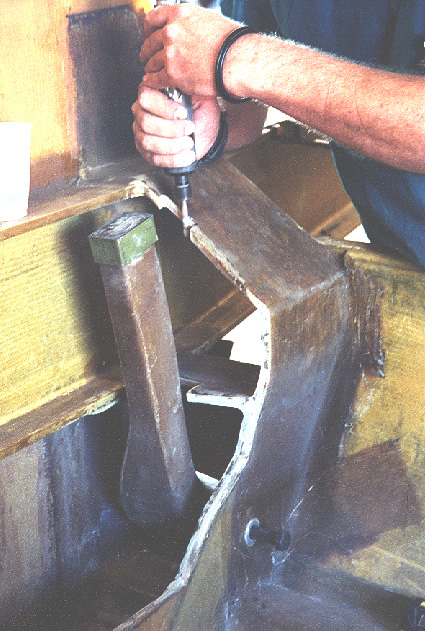
| Holes drilled through gear bulkhead for placement of main gear bushings. | The bushings are fitting into place temporaily, the main gear inserted, pivoting on their bolts and the cant forward and aft is exactly matched side to side. To achieve this, the appropriate edge of the bushing hole is shaved to achieve the exact position of the bushing to have the gear legs line up. | The cutouts from the firewall and gear bulkheads lined up next to the gear bushings. Note the thin layer of plywood forming the core and the tremendous thickness of the layers of fiberglass on either side, like rings of a tree. These layers hold together, confirming the adequacy of the bound between layers. | Gear bushings are installed using structural adhesive and a radius formed along the outer edge with epoxy, milled fiber and cabo. |
|
|
|
|
|
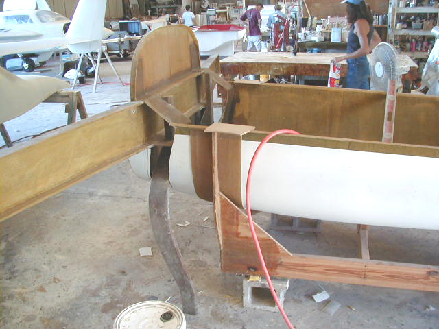
| Gear leg temporarily in position. | Brake line ducts taped to the gear legs. Plastic tubing bound to the legs by a layer of fine BID. The diameter is large enough to allow the passage of the nylaflow brake lines. When these lines have to be replaced they can simply be pulled through and discarded rather than be ground off the legs. | Gear leg preliminary install. Note steel collars on ends of legs. The legs are shown in a retracted position. | Slot in transverse bulkhead shaved to adjust position of leg in down position. |
|
|
|
|
|
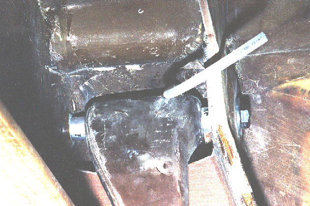
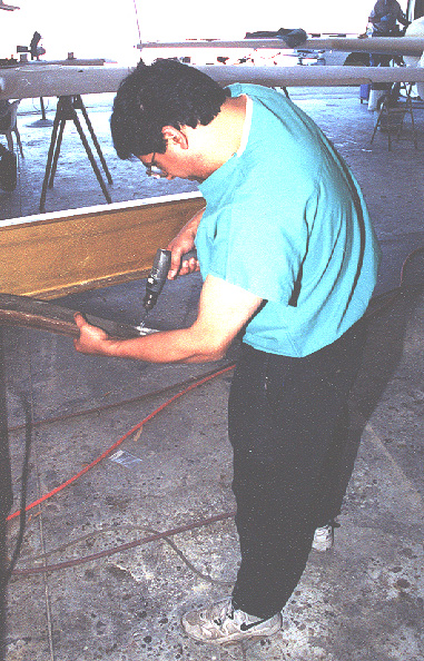
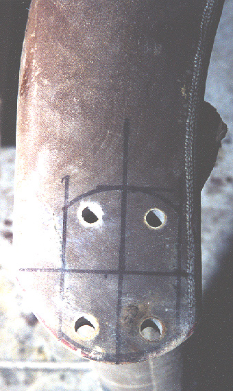
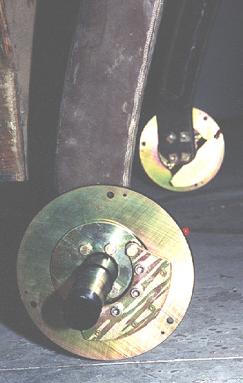
| Gear installed. Note brake line conduit. | Drilling holes for axles. | Holes for axle unit placement. Note that end of gear leg must be rounded off to allow proper fit and placement of wheel. | Axles and brake units attached to gear legs. |
|
|
|
|
|
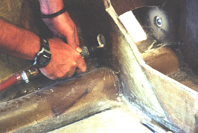
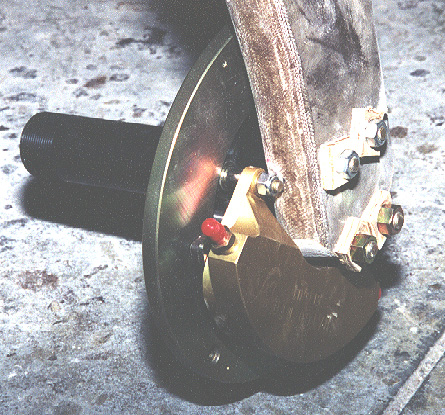
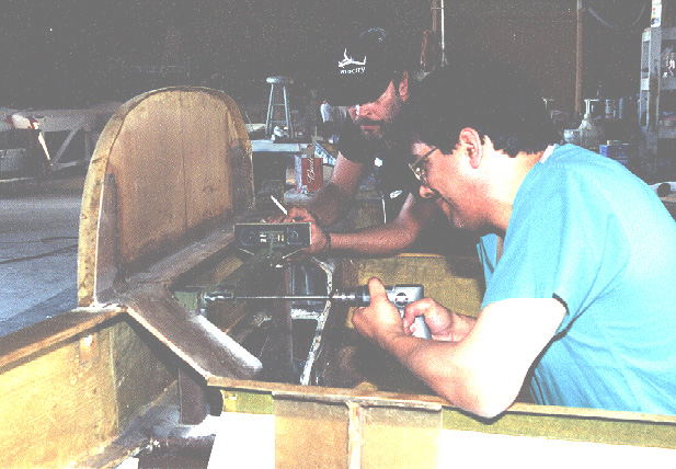
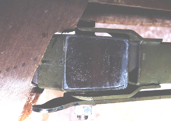
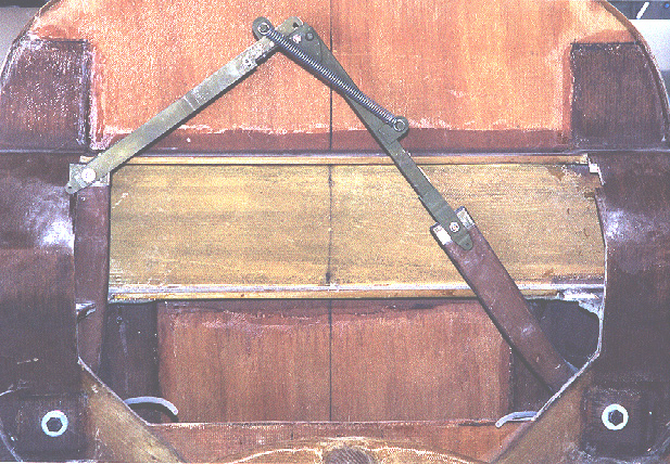
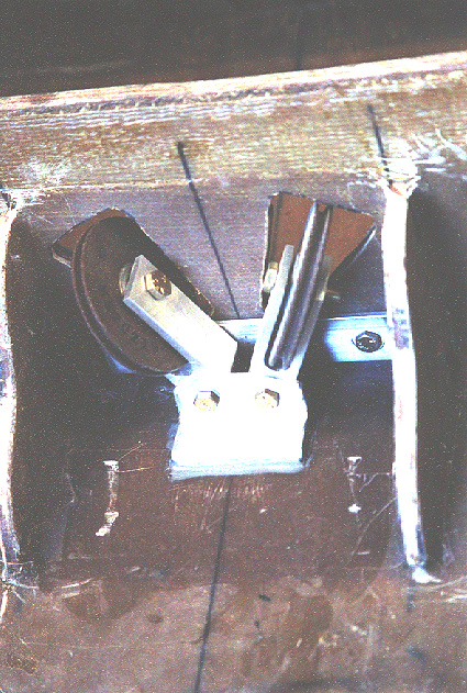
| Closeup of wheel installation. Spacers seen in place for ultimate positioning of gear doors. | This was hard! Drilling holes through the steel collars to attach overhaed linkage. We used the linkage itself, leveled with the bubble level seen in center, as a guide to drill the holes. We drilled in sequential sizes and broke a couple of bits in the process. This stuff is tough! | Closeup of the gear linkage now installed at the steel collar. | Overhead linkage in place. |
|
|
|
|
|
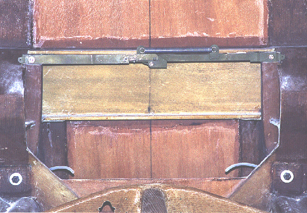
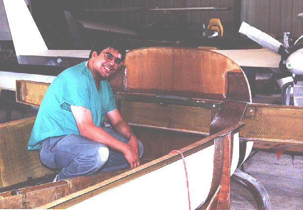
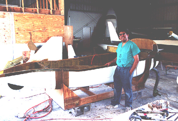
| It took a little work, but the main gear is now installed! | Gear leg on left of photo in up position; gear leg on right of photo shown partially retracted. This should give some sense of how the linkage moves as the gear cycles up and down. | Starting to look less like a canoe! | Pulleys for cables to retract the main gear shown. These are located on the center of the forward face of the gear bulkhead just behing the keel. |
 Comments, questions, and suggestions are welcome! email: rich@rguerra.com
This page visited times.