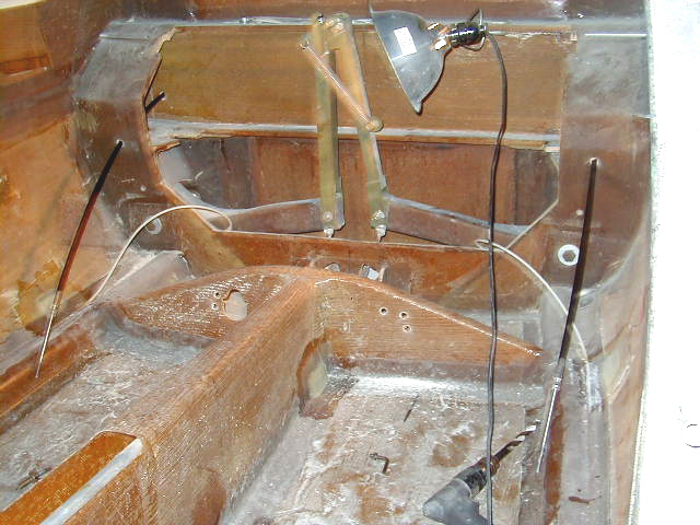


Details of control systems in final stages of construction 9/7/01. Aileron hinges are attached and mated to the wings. The aileron wells on the wings had to be reworked to allow for full excursion of ailerons. Also illustrated are the installation of the aileron and rudder cable and brake control systems and the control stick. Elevator installation illustrated. Details of rudder and elevator mounting illustrated.
|
|
|
|
|
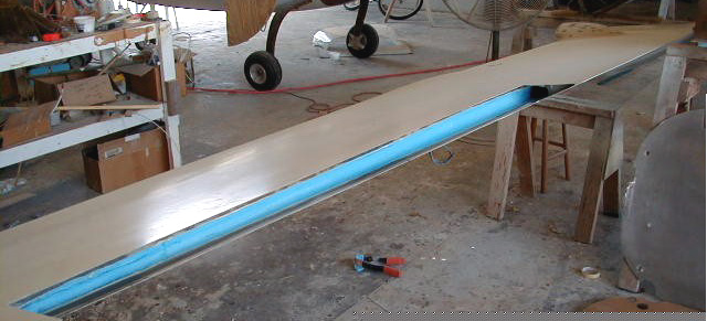
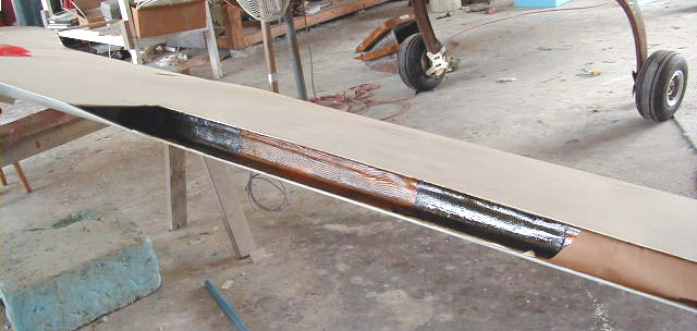
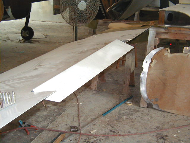
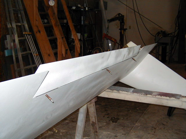
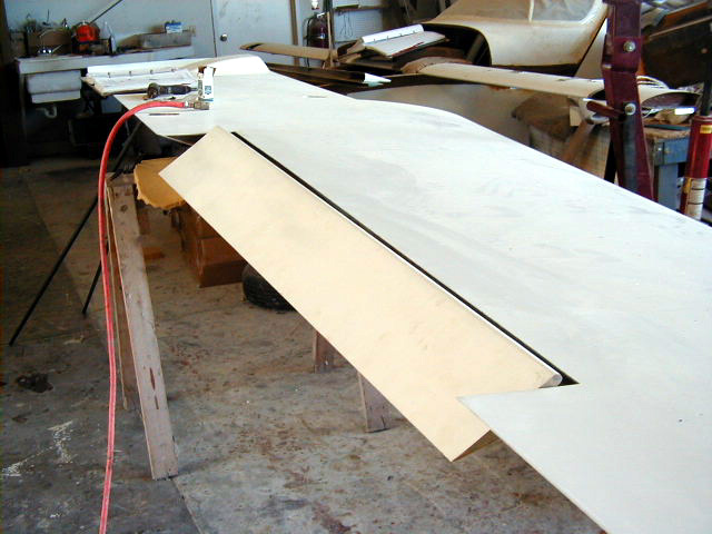
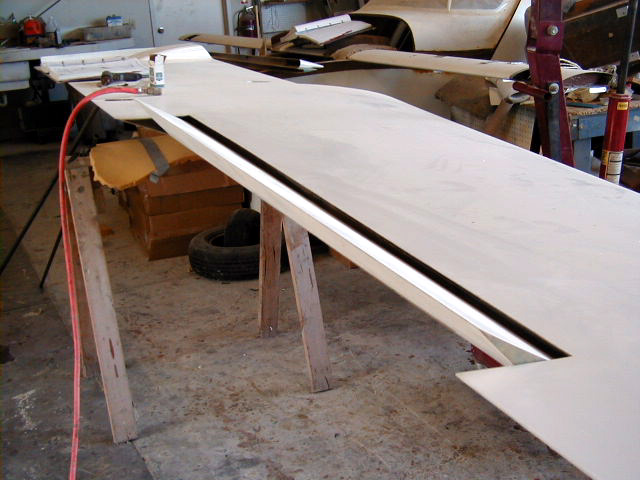
| Aileron wells being reworked to allow full excursion of ailerons. | Aileron well rebuilt. Note carbon fiber at hinge points. | New aileron well. | |
|
|
|
|
|
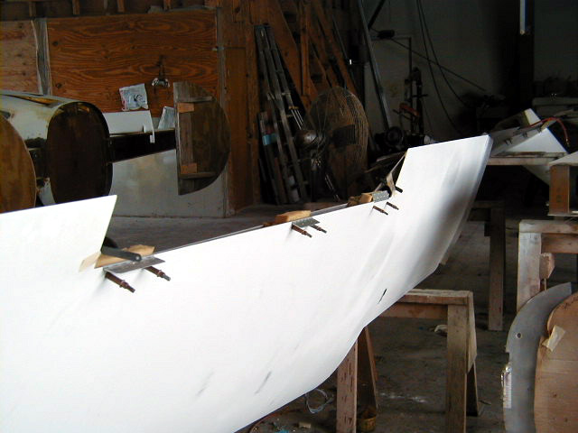
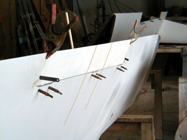
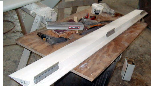
| Installation of aileron hinges. | |||
|
|
|
|
|
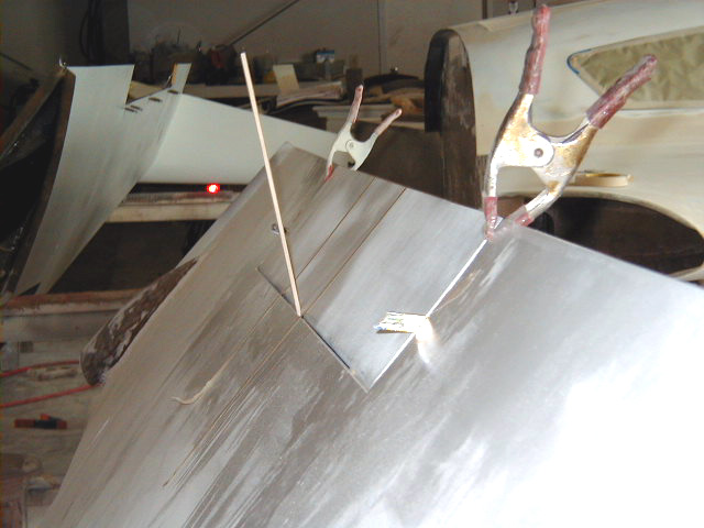
| Aileron in full swing up ... | |||
|
|
|
|
|
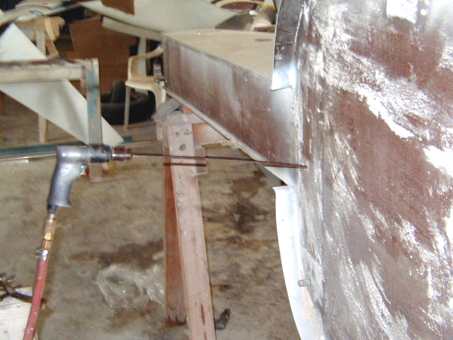
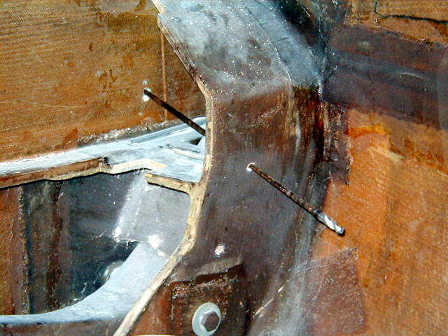
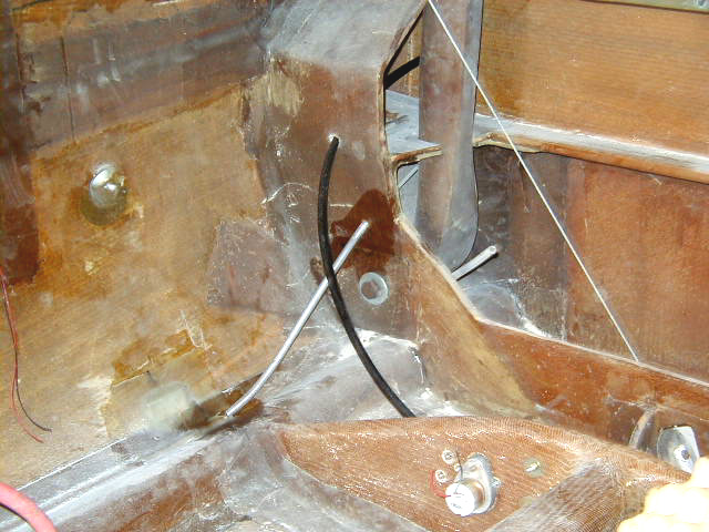
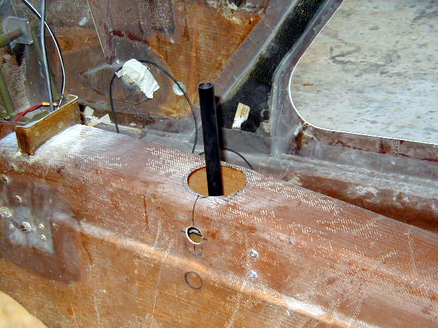
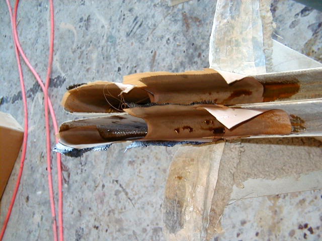
| ... and down! | Drilling holes for aileron cables. | Drilling rig passes through firewall and gear bulkhead. | Aileron cable run through gear box. These are high temperature resistant aileron cables special ordered. |
|
|
|
|
|
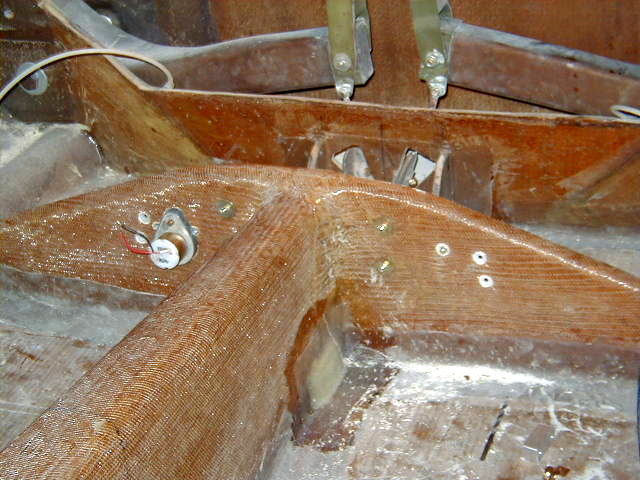
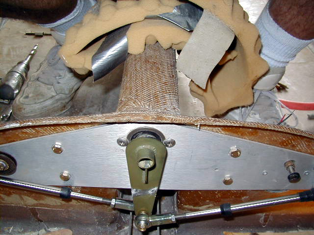
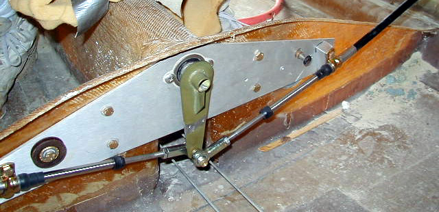
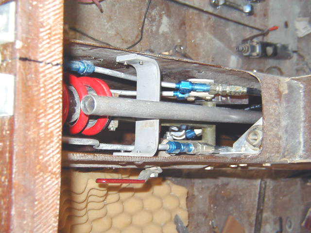
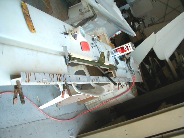
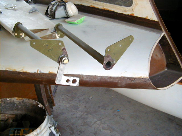
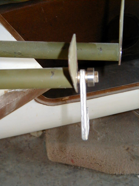
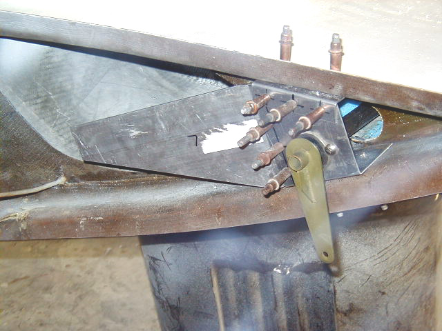
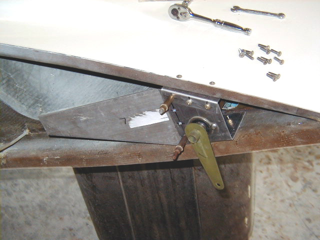
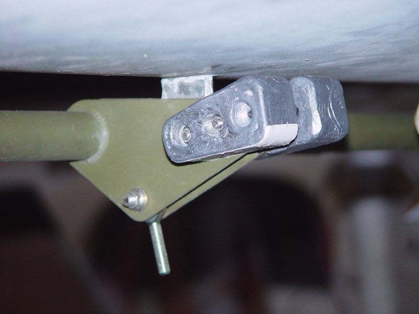
| Aileron bellcrank bracket front. | Aileron bellcrank bracket rear. | Aileron bellcrank bracket mounted on "tail" of keel. | Aileron cable assembly. |
|
|
|
|
|
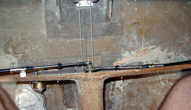
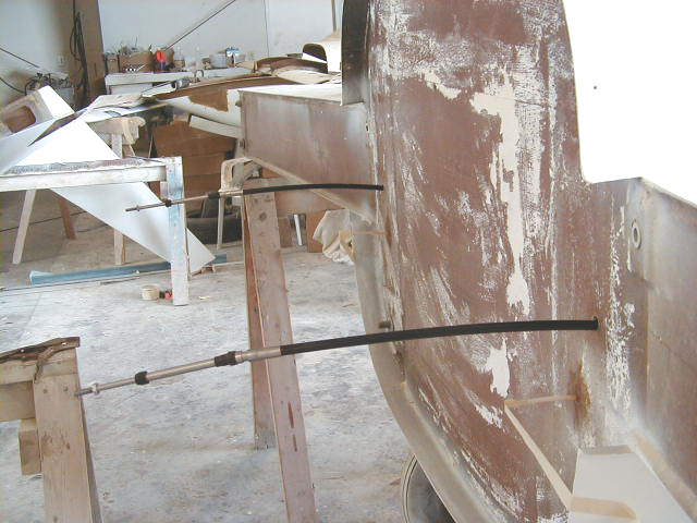
| Aileron cable assembly complete! | Aileron cables running out back of firewall. Note tape holding rudder cable conduits in place as epoxy dures. | ||
|
|
|
|
|
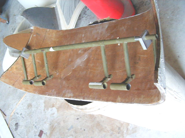
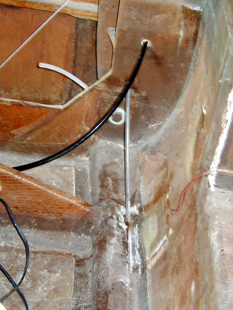
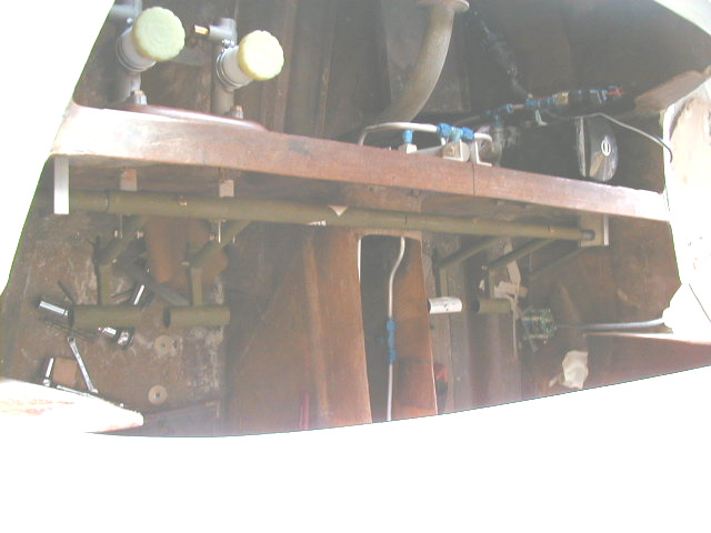
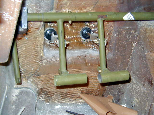
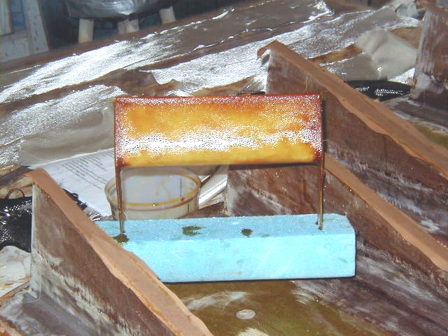
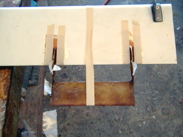
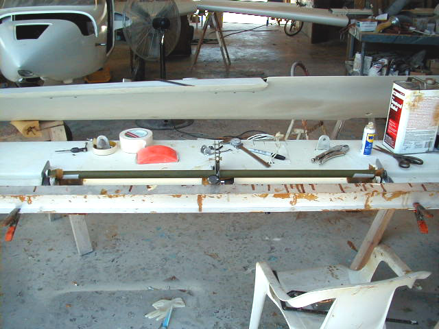
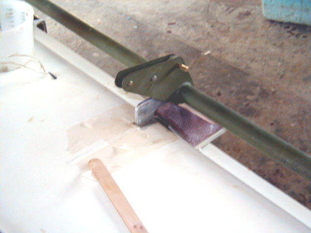
| Rudder pedal assembly (displayed on the underside of the canard cover). | Another Hangar 18 refinement: The rudder cable conduits tend to flex around when they are unsupported. Stiffener tubing made of 3/8" OD aluminium prevents the flwexing and firms up rudder response. | Another view of the rudder conduit stiffening tubing. | Control stick painted black. |
|
|
|
|
|
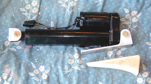
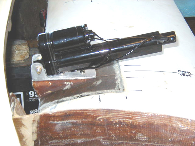
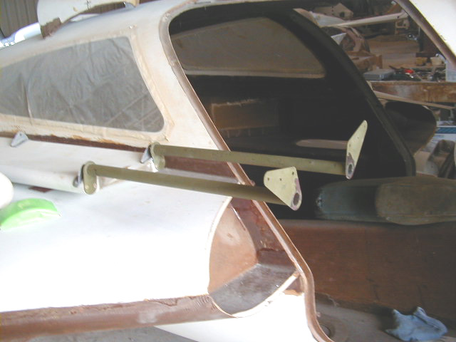
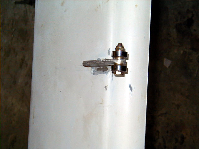
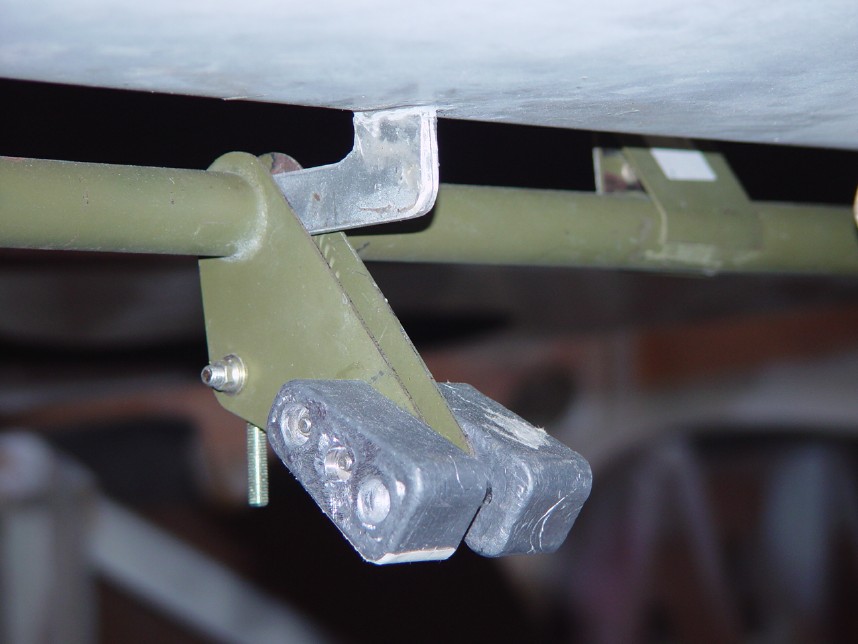
| Sick mounted in position. | Elevator push tube to which the stick is connected. Nosegear overcenter linkage stop also seen. | Pitch trim assembly parts. | Pitch trim test fitted on top of canard. |
|
|
|
|
|
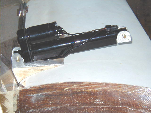
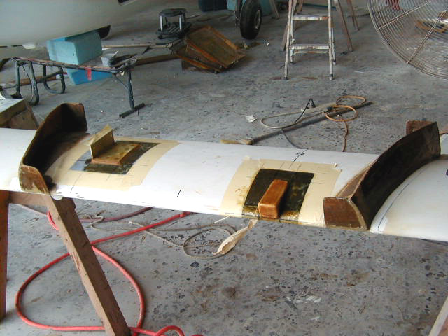
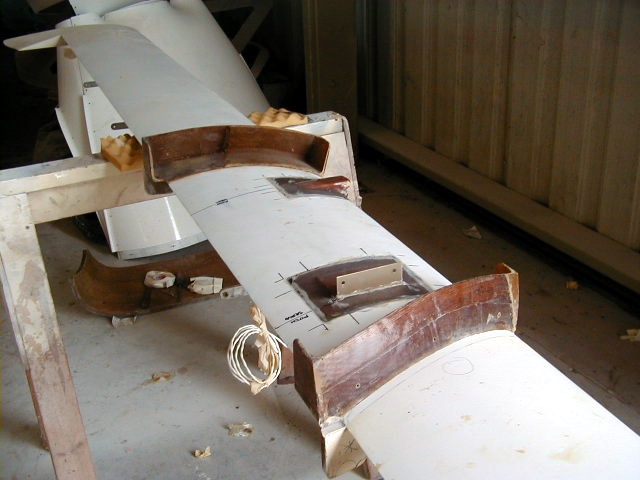
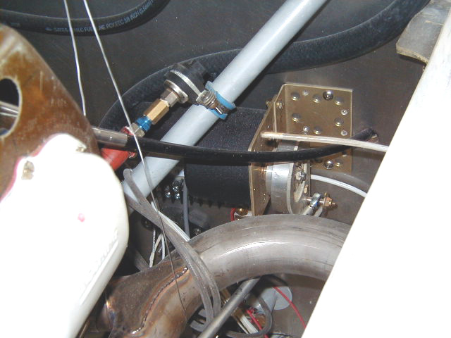
| Pitch trim and pitch servo mounts in place on canard. | Another view pitch trim and pitch servo mounts in place on canard. | Pitch trim motor mounted. | Rudder peddles installed. |
|
|
|
|
|
| Rudder pedals, pilot side. Note links to brake mechanism. | The sparrow strainer installation process. | ||
|
|
|
|
|
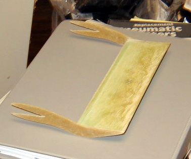
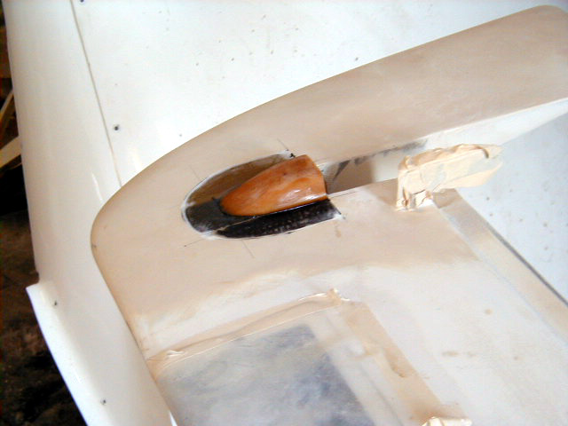
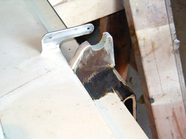
| Anti-ice fairing for outboard elevator weight. | Notch for elevator torque tube. | Setting up elevator torque tube. | |
|
|
|
|
|
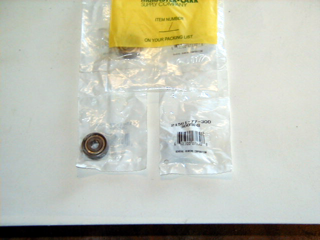
| Bearings for elevator toque tube. | |||
|
|
|
|
|
| Fitting bearings to elevator torque tubes. | Aileron bracket clecoed into place. | ||
|
|
|
|
|
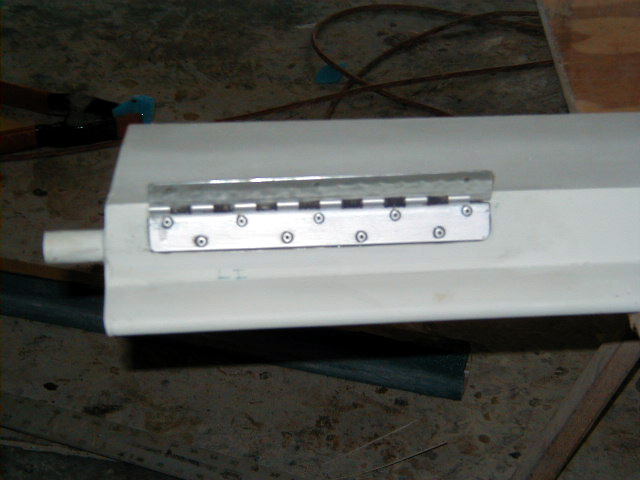
| Aileron bracket mounted. | Re-setting center elevator hinge arm | Re-setting center elevator hinge arm | S-Tec autopilot roll servo mounted on firewall. |
|
|
|
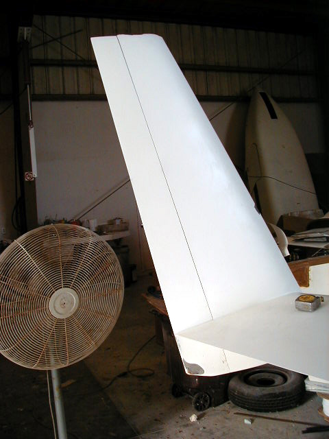
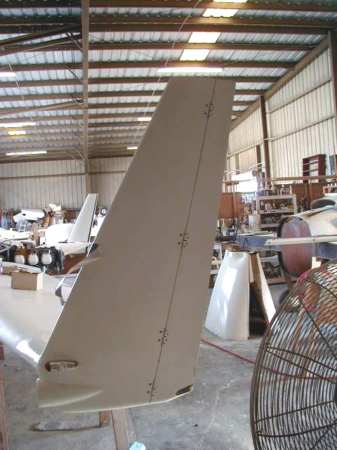
|
|
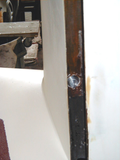
| Rudder return spring. | Rudders now attached! | view of winglet with rudder attached. Final buying shaping of winglet next and seen in Wings II section. | Elevator weights canted just so to avoid impinging on canard when elevator full down position. |
|
|
|
||
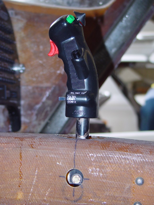
| Weights seen with elevator in full up position. | Infinity stick grip seen mounted. Access port for bolt seen. |
 Comments, questions, and suggestions are welcome! email: rich@rguerra.com
This page visited times.